
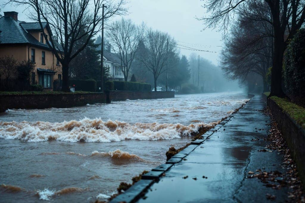
Stormwater drainage design is an essential part of modern hydraulic engineering. A properly designed stormwater system must safely collect, convey and discharge rainfall runoff while reducing the risk of flooding, ponding, erosion and damage to buildings and infrastructure.
Designing that system takes more than selecting a pipe diameter. The engineer has to evaluate rainfall characteristics, contributing catchment areas, surface runoff, design rainfall intensity, time of concentration, peak discharge, pipe capacity, flow velocity, and the hydraulic performance of the whole drainage network.
For relatively small urban catchments, one of the commonly used approaches for estimating peak stormwater runoff is the Rational Method. The same logic sits behind the sewerage and drainage design and hydraulic calculation work we do on building and site projects.
What is stormwater?
Stormwater is water generated by atmospheric precipitation, primarily rainfall and, depending on the location and design conditions, snowmelt.
In urban areas, a significant portion of rainfall becomes surface runoff because natural ground surfaces have been replaced by impervious surfaces such as:
- Building roofs
- Roads
- Pavements
- Parking areas
- Concrete surfaces
- Paved courtyards
The greater the impervious area, the greater the volume and rate of runoff that the drainage system has to manage. Accurate identification of contributing surfaces is therefore one of the first steps in stormwater drainage design.
Determining the drainage catchment area
The first step in a stormwater hydraulic calculation is determining the contributing catchment area.
The catchment may include:
- Roof areas
- Courtyards
- Parking areas
- Roads
- Pavements
- Landscaped areas
- Other surfaces contributing runoff to the drainage system
For a building, the roof can be divided into several drainage zones. Each zone can discharge to a specific rainwater outlet, downpipe or drainage connection. That lets the engineer determine the runoff contribution from each area and size the corresponding drainage components.
Rainfall intensity
One of the most important parameters in stormwater design is rainfall intensity, usually represented by i.
Rainfall intensity is commonly expressed in mm/h. Knowing the total amount of rainfall alone is not sufficient for hydraulic design. The engineer must determine the rainfall intensity corresponding to the relevant:
- Storm duration
- Return period
- Local climatic conditions
Rainfall intensity is commonly obtained from IDF curves: Intensity-Duration-Frequency curves. IDF relationships connect rainfall intensity, storm duration and return period, and they are fundamental to the selection of design rainfall conditions.
For an actual project, rainfall intensity should be based on appropriate local meteorological data and the design criteria that apply at the project location.
Runoff coefficient, C
Not all rainfall becomes direct surface runoff. Part of it may infiltrate into the ground, remain temporarily on the surface, evaporate, or be intercepted by vegetation.
The runoff coefficient, C, accounts for the proportion of rainfall that contributes to runoff. Its value depends on the surface:
- Roofs have relatively high runoff coefficients
- Concrete and asphalt surfaces have high runoff coefficients
- Landscaped areas generally have lower runoff coefficients
- Permeable soils have lower runoff coefficients
When a catchment consists of several different surface types, a weighted average runoff coefficient can be calculated:
Cw = (C1A1 + C2A2 + ... + CnAn) / A
where:
- Cw = weighted runoff coefficient
- C1, C2...Cn = runoff coefficients for individual surfaces
- A1, A2...An = corresponding surface areas
- A = total catchment area
The selected runoff coefficients should be consistent with the applicable design standard or methodology.
The Rational Method
For relatively small drainage catchments, the Rational Method is commonly used to estimate peak runoff.
The basic equation is:
Q = C × i × A
When Q is expressed in m³/s, i in mm/h and A in hectares, the equation becomes:
Q = 0.00278 × C × i × A
where:
- Q = design peak runoff [m³/s]
- C = runoff coefficient [-]
- i = rainfall intensity [mm/h]
- A = drainage area [ha]
The factor 0.00278 is the unit conversion factor for these units.
Example calculation
Consider a drainage catchment with A = 0.20 ha, C = 0.90 and i = 120 mm/h.
Q = 0.00278 × 0.90 × 120 × 0.20
Therefore Q ≈ 0.060 m³/s, or approximately 60 l/s.
This design flow is then one of the primary parameters for sizing the stormwater drainage pipe.
Time of concentration
Another important parameter is the time of concentration, Tc.
Time of concentration is the time required for runoff from the hydraulically most distant point of the catchment to reach the point where the calculation is being performed. It may include overland flow time, inlet or entry time, and flow time through pipes or channels.
It matters because it influences the rainfall intensity selected from the applicable IDF relationship. In general, the critical rainfall intensity used in the Rational Method is associated with a duration related to the catchment's time of concentration. An inappropriate estimate of Tc therefore affects the calculated design discharge directly.
From design flow to pipe sizing
Once the design runoff has been calculated, the next step is to determine whether the selected pipe has sufficient hydraulic capacity.
For gravity drainage systems, the Manning equation is commonly used:
Q = (1/n) × A × R2/3 × S1/2
where:
- Q = flow rate [m³/s]
- n = Manning roughness coefficient
- A = cross-sectional flow area [m²]
- R = hydraulic radius [m]
- S = hydraulic slope [m/m]
For a circular pipe flowing full:
A = πD² / 4 and R = D / 4
Using these relationships, the engineer can evaluate the hydraulic capacity of a selected pipe diameter and determine whether it can safely convey the design discharge.
Flow velocity
Pipe capacity is not the only parameter that must be checked. Flow velocity should be evaluated as well.
If the velocity is too low, sediment and debris may accumulate in the drainage system. If it is excessively high, it may contribute to erosion, increased turbulence, or other hydraulic and operational problems.
Stormwater pipe design should therefore consider flow rate, pipe diameter, slope, velocity and hydraulic capacity together, rather than relying solely on diameter.
Roof drainage design
One of the most common applications of stormwater calculations is the design of building roof drainage systems.
The drainage system can generally be organised as:
Roof catchment → roof drains/gutters → vertical downpipes → horizontal collectors → inspection chambers → discharge point
Each roof drainage zone should be evaluated based on its contributing area and the selected design rainfall intensity. For large roofs, careful positioning of roof outlets and downpipes is particularly important to prevent excessive water accumulation and uncontrolled overflow. The design should also consider emergency drainage arrangements where required by the applicable standards and building design criteria.
Stormwater drainage network design
For larger systems, individual drainage elements are connected into a network. A typical system may include:
- Roof drains
- Downpipes
- Catch basins
- Inlets
- Inspection chambers
- Manholes
- Gravity pipelines
- Open channels
- Outfalls
- Detention or retention facilities
As additional catchments join the network, the contributing flow increases. Downstream sections generally need to be checked for progressively higher design flows. Pipe diameters should still be selected from hydraulic calculations rather than simply increased at every downstream section.
Pipe slope and hydraulic performance
Pipe slope is a critical parameter in gravity stormwater drainage design. It provides the hydraulic gradient required to convey water through the system. A suitable slope should provide sufficient flow velocity while maintaining the required hydraulic capacity.
During design, the engineer should evaluate pipe slope, design flow, pipe diameter, flow velocity, hydraulic capacity, and upstream and downstream levels. The objective is reliable gravity flow with acceptable hydraulic conditions throughout the network.
What happens when a stormwater pipe is undersized?
An incorrectly sized stormwater system can lead to significant operational problems, including:
- Flooding
- Surface ponding
- Manhole surcharge
- Overflow from drainage inlets
- Water accumulation on roofs
- Damage to pavements and landscaping
- Erosion around discharge points
- Overloading of downstream drainage infrastructure
These problems can often be prevented through appropriate hydrological and hydraulic analysis during the design stage.
Hydraulic verification of the system
After the initial design, the entire drainage system should be hydraulically verified. Typical checks include:
- Design flow
- Pipe capacity
- Flow velocity
- Pipe slope
- Hydraulic grade
- Water levels
- Manhole conditions
- Downstream discharge conditions
- Potential surcharge
- Outfall conditions
The objective is not simply to select a pipe diameter, but to verify that the entire drainage system operates safely under the specified design conditions.
Stormwater design and BIM coordination
Modern building projects increasingly rely on BIM and 3D coordination. Stormwater drainage systems should be coordinated with structural elements, architecture, domestic water, sanitary drainage, HVAC, fire protection and electrical services.
BIM coordination helps identify clashes between drainage pipes and other building services before construction begins. That is particularly valuable for vertical rainwater downpipes, underground drainage networks, plant rooms, service shafts, and areas with limited installation space.
Our 2D and 3D modelling work puts stormwater in the same coordinated model as the rest of the building services, rather than leaving it as a separately drafted package.
Why accurate stormwater calculations matter
Stormwater drainage is sometimes treated as a simple pipe-sizing exercise. In reality it requires a combination of hydrology and hydraulics. An accurate design has to answer several questions:
- How much rainfall reaches the drainage system?
- How quickly does the runoff reach the system?
- What is the peak design discharge?
- Can the selected pipe convey that discharge?
- Is the flow velocity acceptable?
- Can the downstream system safely receive the discharge?
Only after these questions have been evaluated can the drainage system be considered properly designed.
Conclusion
Stormwater hydraulic calculations are a fundamental part of drainage and hydraulic engineering. A professional stormwater drainage design typically includes determining the catchment, identifying surface characteristics, selecting runoff coefficients, determining design rainfall intensity, establishing time of concentration, calculating peak discharge, selecting pipe diameters, checking hydraulic capacity with the Manning equation, verifying flow velocity and slope, and checking the performance of the complete network.
A stormwater drainage system should not be designed simply by selecting standard pipe diameters. Every important component should be supported by appropriate hydrological and hydraulic calculations.
From rainfall intensity to final discharge, every stormwater system should begin with a sound hydraulic calculation. That is the approach we take on sewerage and drainage design projects, and as a standalone hydraulic calculation when an existing layout needs to be verified.