
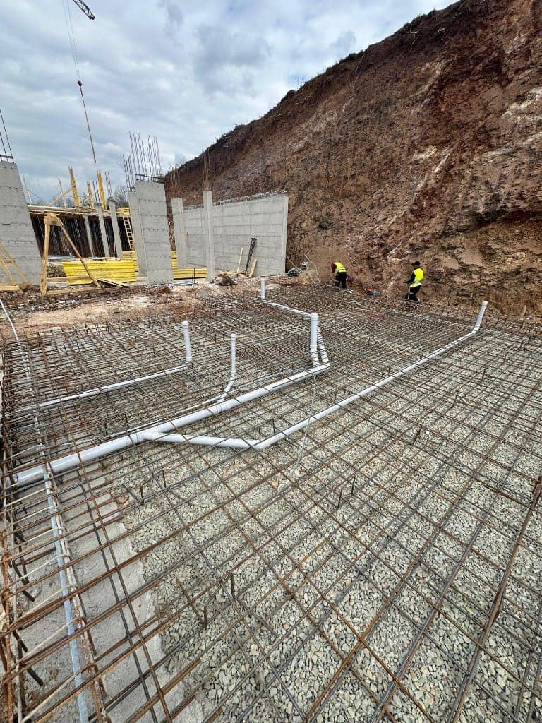
A sanitary sewerage system is one of the most important parts of the plumbing and drainage infrastructure of any building. Its primary purpose is to collect and safely convey wastewater from sanitary fixtures to the public sewer network or to an appropriate wastewater treatment system.
A properly designed sanitary drainage system must provide reliable flow, adequate ventilation, effective protection against blockages, and safe operation throughout the service life of the building. That is the same approach we take on sewerage and drainage design projects, and as a standalone hydraulic calculation when an existing layout needs to be verified.
What does a sanitary sewerage system include?
A building sanitary drainage system may include:
- Toilets (WCs)
- Wash basins
- Showers and bathtubs
- Kitchen sinks
- Washing machines
- Branch drainage pipes
- Vertical soil and waste stacks
- Horizontal drainage collectors
- Inspection chambers and manholes
- Drainage ventilation pipes
- Connection to the public sewer network
All of these components must be designed as an integrated system.
Identifying wastewater sources
The first step in sanitary sewer design is to identify all fixtures and appliances that discharge wastewater into the system.
A typical apartment, for example, may include:
- 1 WC
- 1 shower
- 1 or 2 wash basins
- 1 kitchen sink
- 1 washing machine
Larger buildings may contain dozens or even hundreds of sanitary fixtures. During design it is necessary to determine which fixtures connect to each branch pipe and which fixtures discharge into each vertical drainage stack. That provides the basis for determining the design flow of the sanitary drainage system.
Drainage fixture units
One commonly used approach for sizing sanitary drainage systems is the Drainage Fixture Unit (DFU) method.
Each sanitary fixture is assigned a characteristic drainage load, which is used to determine the total loading of the drainage system. A system serving a small number of fixtures does not have the same hydraulic demand as a system serving a large residential or commercial building.
The total drainage load is therefore determined using the applicable standard, plumbing code or design methodology for the project.
Determining the design flow
After determining the drainage load, the next step is to establish the design flow rate.
The design flow is not necessarily equal to the sum of the maximum discharge rates of all fixtures. It is highly unlikely that every fixture in a building will discharge simultaneously at its maximum flow rate.
For this reason, design standards use statistical methods, loading units, fixture units or probability-based approaches to determine a realistic design flow. This allows the system to be designed efficiently without unnecessary oversizing.
Pipe sizing
Once the design flow has been established, the appropriate pipe diameter can be selected.
For gravity sanitary drainage systems, pipe sizing is influenced by:
- Design flow
- Pipe diameter
- Pipe slope
- Internal pipe roughness
- Flow depth
- Degree of pipe filling
- Flow velocity
One of the commonly used equations for evaluating flow in gravity pipes and open channels is the Manning equation:
Q = (1/n) × A × R2/3 × S1/2
where:
- Q = flow rate [m³/s]
- n = Manning roughness coefficient
- A = flow area [m²]
- R = hydraulic radius [m]
- S = pipe slope [m/m]
The equation allows the engineer to verify whether a selected pipe diameter and slope provide sufficient hydraulic capacity for the design flow.
Sewer pipe slope
One of the most important parameters in gravity sanitary drainage design is the pipe slope.
The slope must be sufficient to maintain gravity flow and reduce the risk of solids settling inside the pipe. At the same time, excessively steep slopes can result in unnecessarily high flow velocities and may affect the hydraulic performance of the system.
Pipe slope should therefore always be evaluated together with pipe diameter, flow rate and velocity.
Flow velocity
The velocity of wastewater inside the pipe must also be checked during the design process.
If the velocity is too low, solids may settle within the pipe, increasing the risk of blockages and maintenance problems. If the velocity is excessively high, other operational and hydraulic issues may occur.
Professional sanitary sewer design should not be based only on the question "Can the pipe carry the required flow?" It should also answer: "Does the pipe convey the design flow at an appropriate velocity and under suitable hydraulic conditions?"
Vertical sanitary drainage stacks
In multi-storey buildings, wastewater is conveyed through vertical sanitary drainage stacks. These stacks collect wastewater from individual floors and convey it downward to the horizontal building drain or building sewer.
When designing vertical stacks, the following should be considered:
- Number of floors
- Number of sanitary fixtures
- Total drainage load
- Stack diameter
- Ventilation requirements
- Horizontal branch connections
- Changes in direction
- Access for inspection and maintenance
The location of drainage stacks should also be coordinated with the architectural and structural design of the building. Proper coordination helps prevent unnecessary structural penetrations and conflicts with other building services.
Sanitary drainage ventilation
An often overlooked component of sanitary drainage design is the ventilation system.
Drainage ventilation plays an important role in:
- Maintaining appropriate pressure conditions within the drainage system
- Protecting water seals in traps
- Reducing the risk of sewer gases entering occupied spaces
- Improving the overall performance of the drainage system
A sanitary drainage system should therefore not be considered simply as a network of pipes carrying wastewater. It is a combined hydraulic and air-pressure system that must be designed as an integrated whole.
Traps and protection against sewer gases
Sanitary fixtures require appropriate protection against the entry of sewer gases into the building. A trap creates a water seal between the fixture and the drainage system.
If pressure conditions within the drainage system are not properly controlled, the water seal can be lost through siphonage or pressure fluctuations. Proper ventilation and appropriate drainage design are therefore essential for maintaining trap seals and protecting indoor air quality.
Changes in direction and access points
During the design process, unnecessary changes in direction should be minimised.
Where significant changes in direction or connections between several branches occur, appropriate access points should be provided to facilitate inspection, cleaning and maintenance.
In external sewer networks, inspection chambers and manholes are commonly used to provide access to the drainage system. Their location and spacing should be determined according to the applicable design standards and project requirements.
Sanitary sewerage in multi-storey buildings
For a multi-storey building, the sanitary drainage system can generally be organised as:
Sanitary fixtures → horizontal branches → vertical stacks → horizontal collectors → inspection chambers → public sewer
Each section of the system must be hydraulically evaluated and appropriately sized. As the drainage system progresses toward the discharge point, more fixtures contribute to the total flow. Consequently, larger pipe diameters may be required in downstream sections of the network.
Pipe diameter should always be determined through hydraulic calculations and applicable design criteria rather than simply increasing the diameter at every downstream section. That is how we size the stacks and collectors on nine-storey building drainage designs.
Hydraulic verification
After the initial pipe sizing, the system should undergo hydraulic verification. Typical checks include:
- Pipe flow capacity
- Pipe slope
- Flow velocity
- Degree of pipe filling
- Hydraulic performance
- Downstream water levels
- Risk of surcharge or backflow
- Accessibility for inspection and maintenance
A properly designed system should be capable of operating reliably under the specified design conditions.
BIM design and coordination with other building services
In modern building projects, sanitary drainage systems should be coordinated with all other building services.
Using BIM and 3D coordination, potential conflicts can be identified between:
- Sanitary drainage
- Domestic water supply
- HVAC systems
- Heating and cooling systems
- Fire protection and sprinkler systems
- Structural elements
- Architectural components
The use of 3D modelling and clash detection helps identify potential problems before construction begins. This is particularly important for vertical service shafts and horizontal drainage collectors, where available space is often limited.
Our 2D and 3D modelling work puts sanitary drainage in the same coordinated model as the rest of the building services, rather than leaving it as a separately drafted package.
Conclusion
The design of a sanitary sewerage system requires the integration of hydraulic calculations, pipe sizing, drainage ventilation, technical coordination and applicable design standards.
A professionally designed system should provide:
- Safe and reliable wastewater removal
- Stable gravity flow
- Reduced risk of blockages
- Appropriate ventilation
- Easy access for maintenance
- Proper coordination with the building structure and other MEP systems
From individual sanitary fixtures to the final connection point, sanitary sewerage design at HydroBer is approached through detailed hydraulic analysis, technical design and coordinated system modelling.
A well-designed sanitary drainage system is not simply a network of pipes. It is an engineered system designed to operate safely, efficiently and reliably throughout the life of the building.